
Swimming Pool Filtration System: Pump & Sand Filter BOM Matching
Match pool pump flow and TDH to turnover, sand-filter area and valve interfaces. Worked calculations and a paired BOM for contractor quotations.
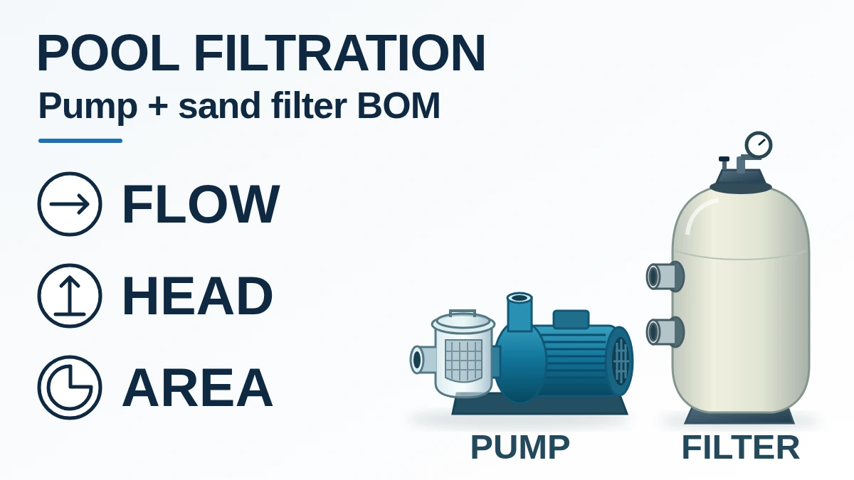
Updated October 2026
A pump and sand filter that fit the same pipe can still leave a swimming pool filtration system short of circulation flow. Match the pump’s flow at total dynamic head to the approved turnover requirement, then check the sand-filter area, valve assembly and operating arrangement on the same BOM.
For a swimming pool filtration system, calculate circulation flow as pool volume divided by the approved turnover period. Select a pump that delivers that flow at the calculated head, and enough online filter area to stay within the project-approved and manufacturer-permitted loading. Check backwash separately. A matching nominal connection size does not prove hydraulic capacity or physical compatibility. The worked example below shows how to write those decisions into a supplier schedule; the assumed values are calculation inputs, not equipment ratings or local design limits.
Input | Source to record | What it controls |
|---|---|---|
Pool volume V, m³ | Approved geometry and water-depth schedule | Required circulation flow |
Turnover T, hours | Consultant requirement and applicable local pool classification | Q = V ÷ T; no Gulf-wide default |
Pump duty Q at H | Hydraulic calculation, operating mode and model curve | Flow at total dynamic head (TDH), speed and frequency |
Filter and valve basis | Effective area, media, approved loading, valve drawing and loss data | Online capacity, backwash duty and physical fit |
Start with pool volume and the approved turnover period
Use the approved pool volume and turnover requirement to calculate the design circulation flow. A turnover period describes the time for a volume equal to the pool volume to pass through the circuit; it does not demonstrate that every parcel of water has been filtered or that disinfection is adequate.
Q: m³/h · V: m³ · T: hours
Hypothetical rectangular pool: V = 20 m × 6 m × 1.5 m mean water depth = 180 m³. With an assumed 6-hour turnover input, Q = 180 ÷ 6 = 30 m³/h. A variable-depth or irregular pool needs its actual volume calculation.
Ask the consultant to identify the current local requirement and the pool classification before using T. A hotel pool, a spa and a private villa pool need their own approval basis. The Abu Dhabi municipal guide discussed in the sources has an explicit scope exclusion for private residential villas; it is not a Gulf-wide specification. Use the hotel and resort project scope to keep each pool’s approvals and supply schedule distinct.
Put flow and TDH on the pump line
The pump must deliver the required flow at the system’s total dynamic head, with its actual electrical and speed variant. Motor horsepower alone cannot establish that operating point.
The OEM pump manual’s performance graph plots water flow against TDH. Give the supplier your hydraulic calculation, including the pipework, fittings, filter, valve and other equipment losses for the stated operating condition. A plant-room elevation difference alone is not a TDH calculation. Record clean-filter and loaded-filter conditions, and the separate backwash path, for engineering review.
Hypothetical head budget at 30 m³/h: H = suction-path loss + return-path loss + filter/valve loss + other equipment loss = 3 + 5 + 4 + 2 = 14 m water head. These are assumed losses at that flow, not measured values. The provisional pump line is therefore “30 m³/h at 14 m TDH”, pending a real hydraulic calculation and model-curve check.
Selection rule: if the offered curve delivers less than the required 30 m³/h at the approved TDH, that selection does not meet this example’s duty. Review the model or approved operating speed. Check excess flow too: a larger pump must not push the filter, valve or other circuit components beyond their permitted conditions.
Check sand-filter area before accepting diameter
Filter loading is flow divided by the effective online filter area. Use the manufacturer’s stated area; an external tank diameter may differ from the effective media-bed diameter.
A: m² · D: effective bed diameter, m · v: m³/(m²·h), equivalent to m/h
For this hypothetical comparison only, assume the engineer sets an allowable loading of 25 m/h and the selected filter/media permits it. Required area = 30 ÷ 25 = 1.20 m². Equivalent single circular bed diameter = √(4 × 1.20 ÷ π) = 1.236 m.
A bed with an effective diameter of 1.20 m has A = π × 1.20² ÷ 4 = 1.131 m²; loading = 30 ÷ 1.131 = 26.53 m/h. It fails the assumed 25 m/h criterion despite its apparently close diameter.
Two effective 0.90 m beds provide A total = 2 × π × 0.90² ÷ 4 = 1.272 m². With equal flow sharing, loading = 30 ÷ 1.272 = 23.58 m/h. If one is isolated and the full flow continues, loading becomes 30 ÷ 0.636 = 47.16 m/h, which fails the same assumed criterion. Two shared-duty vessels do not automatically provide standby filtration.
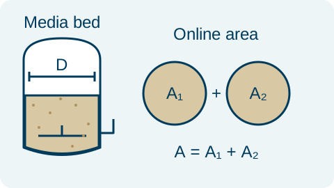
Effective bed area controls loading. In the hypothetical example, removing one of two equal online beds halves the area available at the same total flow.
Selection rule: if Q divided by the online area exceeds the approved loading for that filter and media, increase the approved area or revise the operating flow with the designer. The example’s 25 m/h is not a universal commercial-pool limit. OEM tables give different area/flow combinations for specific configurations.
Confirm the media type, grade, bed depth and quantity alongside the vessel. Obtain the manufacturer’s required backwash flow and check the pump, valve, waste line and drain against that separate duty. A filtration-flow match alone cannot establish backwash capacity. As media loads with debris, pressure and flow change; use the selected equipment’s maintenance criteria and commissioning readings.
Match the valve assembly, not just the inch size
A nominal 1½-inch, 2-inch or 2½-inch label, or a flange designation, is only part of the interface specification. It does not establish that a valve fits the vessel or passes the required flow at an acceptable loss.
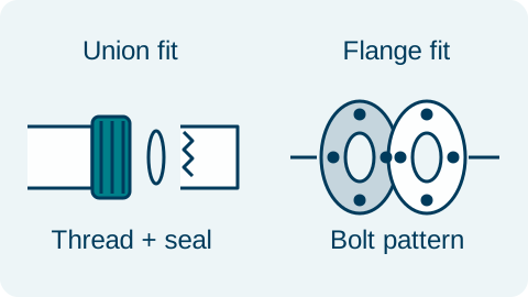
Check the sealing faces and mating geometry. A union/thread/socket interface and a bolted flange require different dimensional records; this schematic gives no interchangeable dimensions.
Record the exact filter and valve part numbers, top- or side-mount configuration, filter-port centre spacing, pump/return/waste port functions, thread standard or solvent-socket size, union tailpiece and seal. For flanges, record the flange standard, nominal designation, bolt pattern and mating face. Check the pipe material and the valve’s pressure, temperature and flow-loss data. Do not equate an imperial label with a metric socket by appearance.
Keep the multiport valve, unions, adapters and media as explicit quotation lines or explicit inclusions. The OEM filter documentation lists separate valve assemblies, including variants supplied with and without plumbing. A vessel-only price cannot be compared directly with a complete filter-and-valve package.
State which equipment runs and which equipment stands by
Write the operating arrangement beside the quantity. “Two pumps” can mean one duty plus one standby, or two units needed together; those arrangements require different checks.
Arrangement | Required check | Dominant Failure Mode & Prevention |
|---|---|---|
One duty pump + one standby | Each pump covers the approved duty alone; record changeover and isolation scope. | A smaller spare cannot maintain duty. Review both model curves and the changeover arrangement. |
Two pumps operating together | Use the combined curve against the system curve. State the one-pump-out duty. | Adding nameplate flows overstates delivery. Shared pipe losses change the operating point. |
Two filters sharing flow | Check total online area and balanced branch flow; recalculate with one isolated. | A half-capacity filter is mistaken for standby capacity. Record the reduced operating limit or provide approved spare area. |
Keep the filtration, one-unit-out and backwash duties visible in the schedule. Final hydraulic, suction-safety, controls and installation approval belongs to the project engineer; the supply comparison must retain that approved basis.
Compare a complete package over the same operating year
Use absorbed electrical input at the same achieved duty and runtime when comparing energy. Motor nameplate output alone is not the electrical consumption figure.
Annual energy = electrical input kW × operating hours/day × days/year
Hypothetical options delivering the same approved duty: 2.2 kW × 12 h/day × 365 days = 9,636 kWh/year; 3.0 kW × 12 × 365 = 13,140 kWh/year. Difference = 3,504 kWh in the same year. Multiply each by the actual project tariff to compare energy cost. These assumed inputs demonstrate the accounting method; the project’s approved operating hours and verified input power control the result.
For the same comparison period, add quoted purchase and installation costs, backwash water and sewer charges, agreed media/service items and labour. Record lost operating time separately if the owner has a documented valuation. Include standby controls, valves, fittings and delivery scope in both offers. The equipment BOM template helps keep those inclusions in the same schedule.
Copy the matched duty into the BOM
Use paired tags so the pump, filter and valve selections stay connected through quotations and approvals. The table below carries the hypothetical 30 m³/h example forward; it does not select a product model.
Tag / quantity | Requirement to put on the line | Document or confirmation still needed |
|---|---|---|
P-01 / 1 duty | 30 m³/h at assumed 14 m TDH | Exact model curve, speed, voltage, phase, frequency, absorbed input and engineer approval |
P-02 / 1 standby | Same approved duty as P-01 when operating alone | Changeover, non-return/isolation arrangement and controls scope |
F-01 and F-02 / 2 online | Illustrative effective diameter 0.90 m each; total area about 1.272 m²; equal branch flow 15 m³/h each | Manufacturer effective area, media type/depth/quantity, allowable filtration and backwash rates, pressure/temperature ratings |
V-01 and V-02 / 1 per filter | Matched valve assembly; size and connection standard TBC | Part number, port functions, centre spacing, union/thread/socket or flange drawing, flow-loss data, included adapters |
Pipework / project quantities | Approved filtration and backwash paths | Branch balancing, drain capacity, instruments, fittings and supply exclusions |
The paired BOM must preserve the same flow, head and online filter area in every supplier revision.
Item | Why we need it | Example format |
|---|---|---|
Approved volume, turnover and pool use | Fix the design flow and approval basis | Pool schedule with country, city and hotel/villa/public classification |
Hydraulic duty and operating modes | Match each pump and filter to the same requirement | Q/TDH schedule, system drawing, duty/standby and backwash notes |
Filter/valve documents and electrical data | Check alternatives and interfaces | Datasheets, dimensioned port drawings, voltage/phase/frequency |
BOM revision and supply boundary | Compare complete quotations | Item tags, quantities, media, valves, adapters, spares and destination |
Send your actual schedule and drawings through the pool equipment package review or request a quotation. Include the operating modes and unresolved fields. PoolProject can flag missing data, coordinate model matching against the buyer-approved requirements and prepare the supply quotation; your engineer retains final design and substitution approval.
Method and sources
Updated 19 October 2026. The equations use volume/time, circular area and electrical-energy arithmetic. All worked values are hypothetical inputs. The technical checks draw on the OEM high-performance pump installation guide (performance curves, printed p. 9), side-mount sand-filter installation guide (operation and model-specific area/flow table, printed p. 1; installation, p. 2), and associated valve specification list, retrieved 19 October 2026. Those documents explain the checks; they do not specify products offered in this article.
The Abu Dhabi municipality’s Guide to the Executive Regulations of Law No. (2) for 2012, issued in 2018, provides the local example of scope and filtration-drawing requirements (printed pp. 2–3). Confirm the current approval requirements with the relevant authority and consultant for the destination and pool type.
NSF’s public equipment overview, consulted 19 October 2026, describes NSF/ANSI/CAN 50 as covering performance validation, operational safety and testing for pool equipment. Use the exact model’s current listing when certification is specified. This scope reference establishes neither certification of a quoted item nor Gulf regulatory acceptance.