
VGB Main Drain Cover Flow Rating, Dual-Drain Spacing & Sump Depth
Check main drain cover flow rating in GPM and m³/h, dual-outlet spacing, tee position and certified sump geometry before releasing a commercial pool submittal.
Updated October 27, 2026
Match the main drain cover flow rating to the complete certified suction outlet fitting assembly and its installed sump geometry. For two interconnected blockable outlets, each assembly must accommodate the full maximum system flow under its manufacturer's selection rule; adding the two cover ratings overstates the usable system rating.
Before releasing a commercial pool drain submittal, reconcile four items: the pump's maximum flow, the exact cover/configuration rating, the distance between drain centers, and the concrete sump section. A matching face size or an “anti-vortex” description does not establish that these four agree.
VGB refers to the United States Virginia Graeme Baker Pool and Spa Safety Act. 16 CFR 1450.3 incorporates ANSI/APSP/ICC-16 2017 with specified exclusions. For a Gulf project, record the local authority's requirements and the consultant's specified standard and edition alongside the manufacturer's instructions.
Read the rating for the complete assembly
A suction outlet fitting assembly, or SOFA, includes the cover/grate and its associated mounting and sump configuration. Its flow rating belongs to that defined assembly. Floor or wall location, suction-pipe size, bottom or side exit, pipe-opening depth and offsets can all affect which rating applies.
Start the submittal with the cover model and complete SOFA configuration identifier. Attach the corresponding certificate or listing and installation drawing. Match the frame, fixing components and permitted sump arrangement before comparing flow numbers.
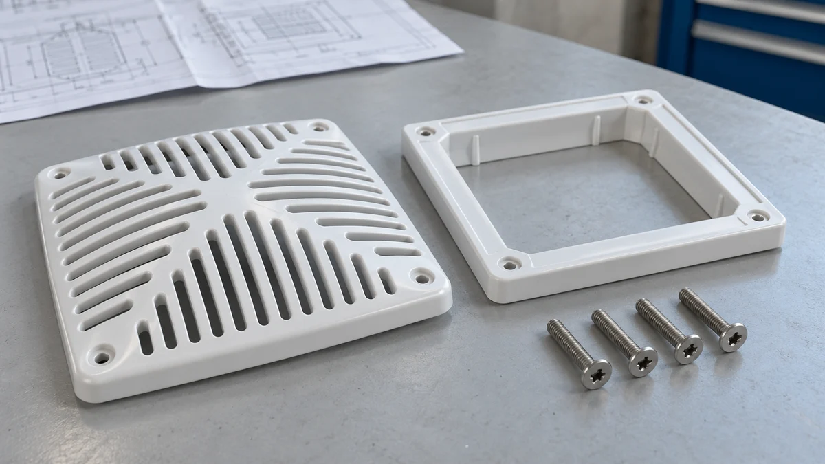
Check the cover, supporting frame and specified fasteners as one assembly. The openings between the ribs determine open area; the outer face dimensions serve a different check.
A configuration-specific commercial benchmark
AquaStar's WAV12WRxxx DS040 specification, revision 04/02/2024, illustrates why a nominal 12-inch cover needs a full configuration check. The following rows are also recorded in NSF's APSP-16 certification listing. Keep the complete identifier with each rating: its letters encode pipe size, pipe-opening depth, ledge geometry, offset and the pipe-size-change limit.
R1–R5 below identify the rows for this comparison. B is the manufacturer's minimum pipe-opening depth, measured using the datum in its drawing. Preserve the drawing's C, D, E and F requirements when using any row.
| Row | Nominal pipe / exit | Position | Minimum B | US GPM | m³/h |
|---|---|---|---|---|---|
| R1 | 2 in / bottom | Floor | 3 in / 76.2 mm | 150 | 34.07 |
| R2 | 3 in / bottom | Floor | 3 in / 76.2 mm | 230 | 52.24 |
| R3 | 3 in / side | Floor | 5.6 in / 142.24 mm | 360 | 81.76 |
| R4 | 4 in / bottom | Floor | 3 in / 76.2 mm | 300 | 68.14 |
| R5 | 4 in / bottom | Wall | 3 in / 76.2 mm | 250 | 56.78 |
Complete SOFA identifiers for R1–R5
R1:
WAV12WR-12f_A-2b_B3_C0.3_D0.7_E4.9_F16R2:
WAV12WR-12f_A-3b_B3_C0.3_D0.7_E4.5_F16R3:
WAV12WR-12f_A-3s_B5.6_C0.3_D0.7_E3_F16R4:
WAV12WR-12f_A-4b_B3_C0.3_D0.7_E3.75_F16R5:
WAV12WR-12w_A-4b_B3_C0.3_D0.7_E3.75_F16
Use the row that matches the installed configuration. R4 and R5 have the same nominal pipe and B depth, but different floor/wall ratings. R2 and R3 change exit orientation, B depth and offset together; their ratings cannot be used to interpolate a new rating for an arbitrary deeper sump. DS040 permits compatible field-built sumps subject to its configuration requirements.
Convert US gallons consistently: m³/h = US GPM × 0.22712470704. For R2, 230 US GPM × 0.22712470704 = 52.24 m³/h, rounded to two decimals. Nominal pipe sizes remain the manufacturer's inch designations; specify the actual pipe standard separately.
Check maximum system flow with one outlet unavailable
For the AquaStar blockable assemblies covered by its installation instructions, multiple outlets piped together in one body of water without isolation valves use this rating check:
System rating = sum of individual SOFA ratings − largest individual rating
For two outlets:
system rating = the smaller of the two ratings.
The cited AquaStar instructions require this system rating to be
greater than the pumping system's maximum flow.
This preserves capacity when one outlet is blocked. Two assemblies each rated at the R2 value give a system rating of 230 US GPM / 52.24 m³/h under that rule. The manufacturer's strict “greater than” condition means a pumping-system maximum equal to that rating does not satisfy its selection wording.
Establish the maximum flow that can reach the suction system from the pump curve and permitted operating conditions. Record pump combinations, speed limits and relevant valve positions. A normal turnover duty is only one operating point. Skimmers, gutters and overflow paths may cease contributing, so the cited instructions exclude their capacity from this suction-system rating check.
Review the outlet rating again after a change that increases circulation flow. Coordinate this with the pump and sand-filter BOM matching guide, where circulation duty and filter capacity are checked together.
Separate drain-center spacing from tee position
For the documented two-blockable-outlet arrangement on the same plane, use at least 3 ft / 914.4 mm center-to-center, subject to the selected manufacturer's instructions. Measure between the outlet centers on the plan. Keep that dimension separate from branch lengths and the position of the common suction tee.
AquaStar's instructions allow closer positioning on different planes under their stated arrangement, such as floor and vertical wall. In the US public-pool context, CPSC's drain-cover guidance requires secondary entrapment protection for a blockable single drain or multiple drains on the same plane less than three feet apart. Have the project professional resolve any such arrangement before procurement or construction.
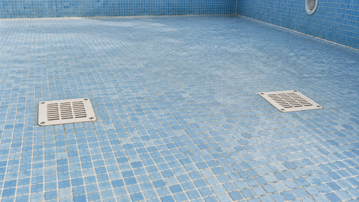
Dimension the two outlet centers on the pool plan, then record their common suction connection and branch routing on the plumbing drawing.
The tee location is a separate design decision. PHTA's July 1, 2025 clarification states that the referenced standards permit the tee anywhere between the two outlets, while requiring compliance with all SOFA manufacturer instructions. A centered tee can be part of an engineered layout; it is not a universal VGB requirement.
Show pipe sizes, routing, fittings and valve arrangement so the designer can check the hydraulic distribution. Equal branch lengths alone do not establish equal flow. Keep individual isolation valves out of the interconnected arrangement used for the rating rule above.
Apply an open-area velocity limit when the project requires it
Check both the certified assembly rating and any applicable local or project velocity limit. A specified 1.5 ft/s / 0.4572 m/s limit uses the cover's actual open area. It is not a universal VGB surface-velocity limit, and the gross face area includes solid ribs and frame material.
Q in m³/h = open area in m² × permitted velocity in m/s × 3600.
In US units: Q in US GPM = open area in in² × velocity in ft/s × 3.1168831.
As an open-area calculation benchmark, Pentair's StarGuard Installation and User's Guide, Chart 2, gives 15.3516 in² of open area. At a jurisdiction-imposed 1.5 ft/s, the calculation is 15.3516 × 1.5 × 3.1168831 ≈ 71.8 US GPM; the manufacturer's chart specifies 71.7 US GPM / 16.28 m³/h. Retain the manufacturer's stated limit when documenting this configuration.
Pentair's corresponding post-May-2021 certificate lists 136 US GPM floor and 88 US GPM wall for its identified StarGuard part families. Those certification values and the velocity-based value answer different checks. Where the 1.5 ft/s condition applies, it is more restrictive for this benchmark. Select commercial-project assemblies against their own approved documents and use the most restrictive applicable limit; an open-area calculation cannot assign a new certified SOFA rating.
Verify the concrete sump from the authorized section
Approve the sump geometry before concrete placement, then verify the finished dimensions against the same drawing. Use the selected configuration's measurement datum, pipe opening, exit orientation, ledges and offsets. A single “net sump depth” dimension does not describe the full flow path.
In the DS040 benchmark, R2 requires B = 3 inches with a nominal 3-inch bottom pipe, while R3 requires B = 5.6 inches with a nominal 3-inch side pipe. These are configuration-specific pipe-opening depths. Applying a blanket 1.5-times-pipe-diameter rule would replace the manufacturer's geometry with a different criterion.
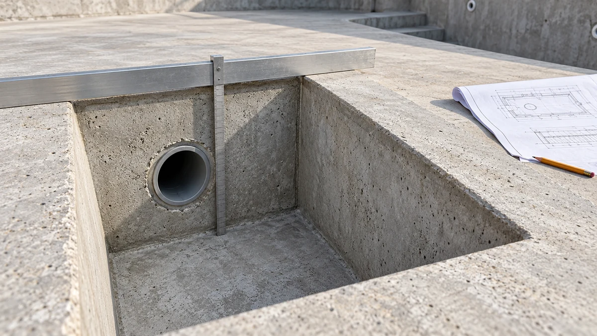
Identify the reference surface, pipe-opening position and net interior geometry on the section. Record each required dimension from the manufacturer's own datum.
Distinguish pipe-opening depth from the 16-inch flow-path category
PHTA's March 2026 clarification of ANSI/APSP/ICC-16 2017 Section 5.7 defines the relevant threshold using a string-line flow path from the entrance of the nearest cover aperture to the closest suction-pipe opening. That measurement determines whether the configuration is below 16 inches or at least 16 inches for the Section 5.7 category.
Keep this string-line measurement separate from vertical pit depth and from manufacturer dimensions measured off the pool's interior finish. The 16-inch classification is not a blanket minimum sump depth. For a manufactured SOFA installed on a field-built sump, retain the manufacturer's authorized configuration and its specific certified rating.
Pipe transitions also need their own check. DS040's F limit governs nearby pipe-size changes: within that limit, its rating is based on the smaller listed pipe size. Increasing the downstream pipe size does not automatically increase the assembly's rating. Identify F from DS040's drawing separately from the Section 5.7 string-line measurement.
Before-pour and finished-sump checklist
- Assembly identity: exact cover, frame, fixing system and complete SOFA configuration code match the submitted certificate and instructions.
- Section geometry: clear interior dimensions, finished-surface datum, pipe-opening depth, ledges and offsets match the authorized drawing, allowing for the specified finish build-up.
- Pipe connection: size, standard, exit orientation and nearby reductions or enlargements match the applicable rating row and installation limits.
- Outlet plan: both centers, their separation, branch routes and common suction connection are dimensioned; the valve arrangement preserves the required interconnected system.
- Flow acceptance: the pump operating envelope meets the manufacturer's system-rating condition and any additional applicable hydraulic or velocity limits.
Resolve a mismatch before releasing the concrete detail. For an existing sump, have the qualified project professional assess the measured geometry against an authorized assembly configuration before accepting a replacement cover.
Keep the handover and procurement documents together
The handover should retain the exact model and certificate, installation instructions, approved plan and section, installed-component dates, specified service life and inspection record. Use the selected model's service-life requirements for each component. Damaged, missing or loose covers and associated components require correction before bathers use the pool.
For document and BOM review, send the circulation pump's maximum flow, the drain cover's face dimensions and rated flow, the concrete sump's net dimensions and both drain centers. Include the jurisdiction/design basis, supporting pump curve, complete SOFA code, certificate, manufacturer section and pipe/valve arrangement so the figures can be checked together.
Use the pool equipment package review to coordinate those records with the pump schedule. For the wider fixture and metalwork package, include the related drawings with the pool accessories scope. Keep the consultant's design acceptance with the project submittal and use the project quotation contact to send the supply-review package.
Reference documents for the submittal
- CPSC: Pool and Spa Drain Cover guidance and 16 CFR 1450.3: United States requirements and incorporated standard.
- PHTA, July 1, 2025 clarification, section 3: tee location; March 2026 Section 5.7 clarification: string-line flow path and field-built sumps.
- AquaStar, WAV12WRxxx DS040, revision 04/02/2024, pages 1–2; NSF APSP-16 listing for the exact WAV12WR configurations; AquaStar Blockable SOFA Installation, Operation, and Maintenance Instructions, IN021-062724, page 1.
- Pentair, StarGuard Installation and User's Guide, Charts 2–3 and installation requirements; StarGuard Certificate of Compliance after May 2021: open-area and floor/wall rating benchmark.