
Salt Chlorinator Flow Switch Troubleshooting: Minimum Pipe Velocity, Gas Trap Loop, and Bypass Sizing
Troubleshoot salt chlorinator flow switch trips, check minimum flow rate and pipe velocity, size commercial bypass manifolds, and configure horizontal gas trap loops.
Updated
Start a salt chlorinator flow switch troubleshooting review by checking the minimum cell flow rate, upstream straight-pipe length, bypass manifold configuration, and gas-trap orientation against the selected manufacturer manual. Keep each hydraulic and electrical requirement attached to the specific chlorinator model when completing the sanitation section of your pool equipment package.
Check minimum flow rate and upstream straight-pipe length
Verify the operating flow window, straight-pipe run before the cell inlet, and post-heater distance for the selected inline salt chlorine generator:
Pentair IntelliChlor SCG is designed to operate with water flow rates from 25 +/- 5 gallons per minute (gpm) up to 105 gpm.
For water flow rates over 80 gpm, Pentair IntelliChlor SCG requires a bypass loop, including installations with in-floor cleaning systems or booster pumps.
For best flow sensing, Pentair IntelliChlor SCG requires at least 12"-18" of straight pipe in front of the cell inlet.
Pentair IntelliChlor SCG should be installed at least three (3) feet away from the heater outlet.
Pentair IntelliChlor SCG pipe couplings are Schedule 80 with a maximum pressure rating of 75 psi at 70° F (21° C).
Pentair IntelliChlor Plus and LT units require 25 GPM (94.6 LPM) minimum flow to activate the internal flow switch inside the SCG.
Pentair IntelliChlor Plus and LT units have a maximum flow of 80 GPM (302.8 LPM), above which a bypass should be used to ensure best flow sensing.
When the sensor module needs replacement, the system generates WARNING "SYS OFF SENS ERR"; the replaceable sensor module includes conductivity, temperature, and flow in one unit.
Pentair iChlor SCG is designed to operate with water flow rates from 20 to 105 gpm (75 to 397.5 lpm), and flow rates over 80 gpm (302.8 lpm) must use a bypass loop.
Pentair iChlor SCG requires at least 12 - 18 in. (30.5 - 45.7 cm) of straight pipe in front of the cell inlet for best flow sensing.
Pentair iChlor SCG should be installed at least 3 ft. (0.9 m) away from the heater outlet.
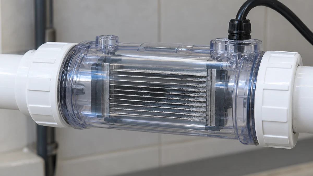
Provide the specified straight pipe run upstream of the inline cell unions and sensor connection on the return piping drawing.
For heat-exchanger and thermal equipment placement on the return line, continue with pool chiller and heat pump BOM specification.
Review external flow switch tee plumbing and wiring
For Hayward AquaRite installations, keep the tee pipe size, upstream straight-pipe length, LED delay behavior, and replacement cable termination together on the submittal:
Hayward AquaRite electrolytic cell and flow switch tee fitting are designed to be plumbed into 2" (51mm) PVC pipe, with adapters usable for 1½" (38 mm) plumbing.
Hayward AquaRite requires at least a 12" (30.5 cm) straight pipe run upstream of the flow switch, and if the switch is plumbed after the cell, the cell can be counted as the 12" (30.5 cm) of straight pipe.
On Hayward AquaRite, an illuminated NO FLOW LED indicates no water flowing and chlorine generation stops, while a flashing NO FLOW LED indicates a 15-60 second time delay period.
For non-digital display units using the Hayward GLX-FLO-RP 4 conductor cable, the yellow and black wires are cut off and not used, while the green and red wires connect to the terminal strip.
Mark the flow-switch tee position, flow direction arrow, and straight-pipe run separately on the piping layout. Keep each model's flow requirement attached to its own manual.
Compare pipe velocity benchmarks and commercial bypass manifolds
Check main recirculation pipe velocity guidance alongside the local branch flow required by commercial chlorinator manifolds:
MAHC Annex states that recirculation discharge piping water velocities should not exceed 8 feet (2.4 m) per second, and velocities of 6 to 8 feet (1.8 m to 2.4 m) per second are recommended.
MAHC Annex Section 4.7.1.7.2.2 states that the maximum velocity in suction piping is 6 feet (1.8 m) per second.
PWTAG Swimming Pool Water Code of Practice specifies that good engineering practice pipe velocities are suction 1.5m/sec and delivery 2-2.5m/sec.
For main circulation duty and filter vessel matching, review swimming pool filtration pump and sand filter BOM matching.
Check commercial bypass manifold and VSP throttling procedures
Record the plumbing method, strainer maintenance schedule, rectifier cooling line, and variable-speed pump calibration steps for the selected commercial system:
ChlorKing commercial saline chlorination systems (Mini, Chlor, and Classic Series) are NSF-50 and UL-1081 listed.
ChlorKing commercial saline chlorination systems require a minimum of 20gpm of flow through the cell to produce the rated amount of chlorine.
When using ChlorKing pressure drop plumbing method [1], unfiltered water passes through the cell and the included strainer must be cleaned at least 1 time per week to prevent flow switch deactivation.
ChlorKing commercial plumbing parts include a 1” clear bowl strainer with 20 mesh and a PVC 1” ball valve Sch 40.
ChlorKing commercial systems require plumbing a 3/8” cooling line into box 3 (rectifier) using filtered water so the heat sink cools critical components.
Solaxx Model SALT340A Manifold Assembly has 2 inch PVC pipe connections, a Maximum Operating Pressure of 50 psi, and an Operating Flow Range of 20-100 gpm.
For variable speed pumps on the Solaxx SALT340A manifold, adjustments are made at the most commonly used filtration setting (usually about 2500 RPM) by starting the pump with the ball valve closed 90% to trigger the flow switch light.
When calibrating the Solaxx SALT340A manifold ball valve, there is a delay of 5-10 seconds before the flow switch light goes off as the valve is opened incrementally.
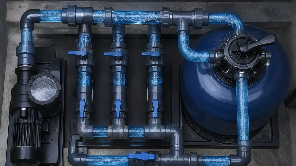
Mark the main-line throttling valve and branch isolation valves across the parallel bypass manifold on the piping detail.
Record the lowest programmed variable-speed pump filtration setting and the bypass valve position on the commissioning sheet.
Configure horizontal inverted-U gas trap loops
For chlorinator cells that rely on an upper-housing gas trap and electronic sensor probe, follow the manufacturer's horizontal or vertical manifold geometry:
AstralPool E-Series chlorinator cells may fail if cell pressure exceeds 250kPa and/or water temperature exceeds 40 degrees Celsius.
AstralPool E-Series cell must be installed horizontally with water connections pointing downwards to create a safety gas trap, and isolation valves must not be installed on the inlet or outlet of the cell.
AstralPool E25 Series cells have a fail-safe negative charge sensor that monitors flow and salt levels, where calcium deposits or debris can cause a low salt or no flow indication.
QuikChlor RP30HD horizontal cell installation requires a 90 degree 2 inch PVC elbow plumbed directly onto both ends of the cell facing vertically downwards to form the inverted ''U''-shaped physical gas trap.
In QuikChlor RP30HD vertical cell installation, a water by-pass manifold maintains the physical gas trap and it is important that water enter the dead leg (cell-free side) and pass downwards through the end of the cell with the large lock nut in the live leg.
QuikChlor RP30HD must be installed on the pool return line downstream of the pump, filter, solar system, heater, or other receptacles where in excess of 2 litres of gas could accumulate, with 30 cm of free space for cell removal.
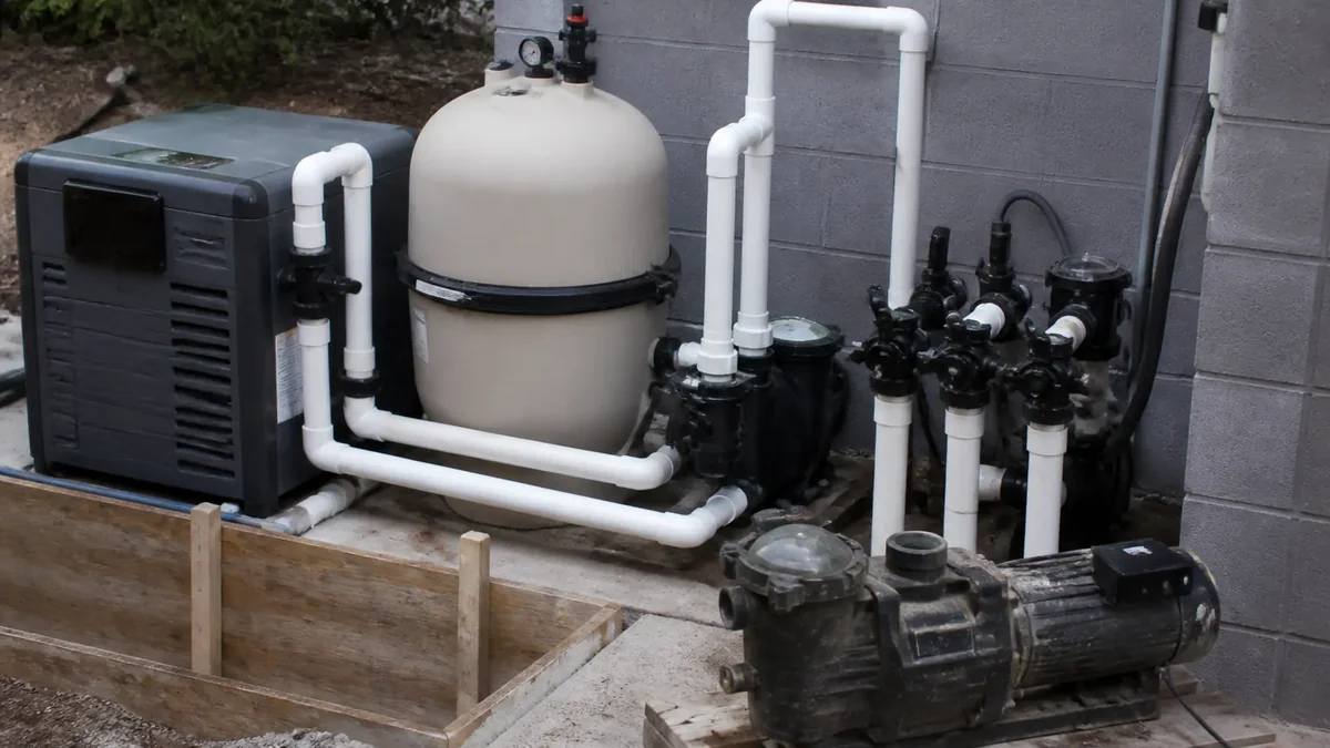
Show the vertical return-line loop elevation and downstream routing past the filter and heater on the equipment pad drawing.
Show the downward-facing elbow orientation, cell removal clearance, and absence of cell isolation valves on the elevation drawing where applicable.
Verify dual electrical interlocks and challenge testing
For commercial aquatic venues, check the certification and dual-interlock requirements alongside the commissioning test protocol:
Under MAHC 4.7.3.2.1.2, aquatic facility electrolytic chemical generators and automated controllers shall be certified, listed, and labeled to NSF-ANSI 50.
Under MAHC 4.7.3.2.6.6 and 4.7.3.2.6.7, salt electrolytic chlorine generator units shall be certified, listed, and labeled to UL 1081 by an ANSI-accredited certification organization and interlocked per MAHC 4.7.3.2.1.3.
Under MAHC 4.7.3.2.1.3 applicability for new or substantially renovated aquatic venues and within 1 year of adoption for existing facilities, chemical control and feed systems shall disable all chemical feeders in a low or no flow condition via an electrical interlock using at least two of: (1) pump power monitor, (2) return-line flow meter/flow switch/pressure switch, or (3) controller flow meter/flow switch.
PHTA RWQC Electrical Interlock Fact Sheet recommends conducting monthly challenge tests, including a backwash cycle at least once per month, to verify interlock safety switch, sensors, and alarms.
PHTA RWQC Electrical Interlock Fact Sheet states that after an interlock trip is corrected, the system should operate correctly for at least 5 minutes before bathers return to the water.
Coordinate electrical interlock wiring with the control panel schedule in pool equipment voltage and frequency.
Track cold-water cutoffs, electrode hours, and scale cleaning
Check water temperature cutoffs, rated electrode service hours, and acid-cleaning mixtures when diagnosing recurring low-flow or low-output warnings:
When pool water temperature falls below 52° F, ±3° F (11° C, ±1.67° C), the Pentair IntelliChlor SCG temperature sensor switches the unit off and illuminates the COLD WATER light.
Cold water below 50ºF causes Hayward AquaRite to stop generating chlorine with the Generating LED flashing.
ChlorKing titanium electrode warranties are not honored if operated in water temperatures lower than 59 degrees F or salt concentration lower than 3000 ppm.
Pentair IntelliChlor SCG is designed to operate for approximately 10,000 hours before replacement is needed, or roughly five (5) years of average use.
ChlorKing advises that titanium electrodes must be replaced every 15,000 hours of operating time.
Pentair IntelliChlor Plus and LT units have built-in polarity reversal every 3 hrs to minimize scale build up.
Pentair recommends that every two (2) months the IntelliChlor SCG be removed and inspected for scale formation and/or debris on the cell blades.
Pentair IntelliChlor SCG acid cleaning mixes one (1) quart of muriatic acid with one (1) gallon of tap water in a plastic bucket.
During acid cleaning, acid must not be left in the Pentair IntelliChlor SCG for more than thirty (30) minutes because excessive acid washing damages the blades.
Hayward AquaRite mild acid washing uses a 4:1 solution of water to muriatic acid (one gallon of water to one quart of muriatic acid), always adding acid to water.
AstralPool E-Series cells are cleaned by turning the cell upside down and filling it with a mix of 1 part Hydrochloric acid to 10 parts water.
Keep the selected manufacturer's inspection interval and acid-dilution procedure in the plant-room maintenance log.
Prepare the sanitation plumbing and interlock submittal
Attach the following records when submitting your sanitation schedule through Drawing and BOM Review or with your pool equipment package enquiry:
- Main return pipe diameter, minimum variable-speed pump filtration flow, and maximum system flow rate.
- Selected salt chlorinator model, rated cell flow range, and upstream straight-pipe length before the cell or flow switch tee.
- Bypass manifold layout, main-line throttling valve type, strainer mesh detail, and rectifier cooling line connection where required.
- Horizontal or vertical gas-trap loop elevation detail and cell removal clearance.
- Electrical interlock schematic showing the pump power monitor, return-line flow switch, and controller interlock wiring.
- Cell inspection interval, acid-wash dilution procedure, and spare sensor or electrode schedule.
Request a quote with your piping schematic and equipment schedule attached.
Sources
- Pentair — IntelliChlor Salt Chlorine Generator Installation and User's Guide
- Pentair — IntelliChlor Plus and LT Salt Chlorine Generators FAQ
- Pentair — iChlor Salt Chlorine Generator Installation and User's Guide
- Hayward — AquaRite Series Owner's Manual
- Hayward — GLX-FLO-RP Replacement Flow Switch Owner's Manual
- ChlorKing — Saline Chlorination System User's Guide
- Solaxx — Model SALT340A Manifold Assembly Installation and Operation Manual
- AstralPool — E-Series Salt Chlorinator Installation and Operating Instructions
- QuikChlor — RP30HD Salt Chlorinator Installation and Operating Manual
- US CDC — Model Aquatic Health Code Code Language and Annex
- PWTAG — Swimming Pool Water Code of Practice
- PHTA RWQC — Electrical Interlock Fact Sheet